
汽车电路图是利用图形符号和文字符号,表示汽车电路构成、连接关系和工作原理,而不考虑其实际安装位置的一种简图。为了使电路图具有通用性,便于进行技术交流,...
开关电路中的门铃电路
接线图
2023年10月21日 14:51 98
admin
相关电路图:
4093B
No. 1: 门铃电路
By Rev. Thomas Scarborough
Cape Town
E-mail scarboro@iafrica.com
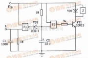
Figure 1 represents a cheap and simple Gate AlARM, that is intended to run off a small universal AC-DC power supply.
IC1a is a faST oscillator, and IC1b a slow oscillator, which are combined through IC1c to emit a high pip-pip-pip warning sound when a gate (or window, etc.) is opened. The circuit is intended not so much to sound like a siren or warning device, but rather to give the impression: "You have been noticed." R1 and D1 may be omitted, and the value of R2 perhaps reduced, to make the Gate Alarm sound more like a warning device. VR1 adjusts the frequency of the sound emitted.
IC1d is a timer which causes the Gate Alarm to emit some 20 to 30 further pips after the gate has been closed again, before it falls silent, as if to say: "I'm more clever than a simple on-off device." Piezo disk S1 may be replaced with a LED if desired, the LED being wired in series with a 1K resistor.
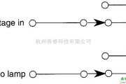
Figure 2 shows how an ordinary reed switch may be converted to close (a "normally closed" switch) when the gate is opened. A continuity tester makes the work easy. Note that many reed switches are delicate, and therefore wires which are soldered to the reed switch should not be flexed at all near the switch. Other types of switches, such as microswitches, may also be used.

相关文章
- 详细阅读
-
教你怎么看电路图,各种电路图形符号大全详细阅读
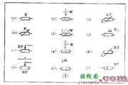
电子设备中有各种各样的图。能够说明它们工作原理的是电原理图,简称电路图。电路图有两种,一种是说明模拟电子电路工作原理的。它用各种图形符号表示电阻器、电...
2024-04-26 64 电路图
- 详细阅读
- 详细阅读
-
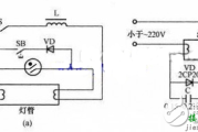
开关电路中的与非门组成的触摸式延时开关电路原理与设计详细阅读
如图所示是用CMOS与非门组成的触摸式延时开关,能延时大约10秒,常用于走廊里路灯、家庭门灯的自动控制。 与非门组成的触摸式延时开关电路&nbs...
2024-04-15 77 开关电路
- 详细阅读
发表评论