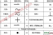
汽车电路图是利用图形符号和文字符号,表示汽车电路构成、连接关系和工作原理,而不考虑其实际安装位置的一种简图。为了使电路图具有通用性,便于进行技术交流,...
MSP430 按键程序 (含电路图及源代码)
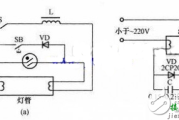
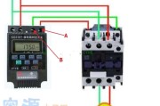
接线图
2023年10月06日 20:53 115
admin
#i nclude < msp430 x14x.h>
void Init_Port(void)
{
//将P1口所有的管脚在初始化的时候设置为输入方式
P1DIR = 0;
//将P1口所有的管脚设置为一般I/O口
P1SEL = 0;
// 将P1.4 P1.5 P1.6 P1.7设置为输出方向
P1DIR |= BIT4;
P1DIR |= BIT5;
P1DIR |= BIT6;
P1DIR |= BIT7;
//先输出低电平
P1OUT = 0x00;
// 将中断寄存器清零
P1IE = 0;
P1IES = 0;
P1IFG = 0;
//打开管脚的中断功能
//对应的管脚由高到低电平跳变使相应的标志置位
P1IE |= BIT0;
P1IES |= BIT0;
P1IE |= BIT1;
P1IES |= BIT1;
P1IE |= BIT2;
P1IES |= BIT2;
P1IE |= BIT3;
P1IES |= BIT3;
_EINT();//打开中断
return;
}
void Delay(void)
{
int i;
for(i = 100;i--;i > 0) ;//延时一点时间
}
int KeyProcess(void)
{
int nP10,nP11,nP12,nP13;
int nRes = 0;
//P1.4输出低电平
P1OUT &= ~(BIT4);
nP10 = P1IN & BIT0;
if (nP10 == 0) nRes = 13;
nP11 = P1IN & BIT1;
if (nP11 == 0) nRes = 14;
nP12 = P1IN & BIT2;
if (nP12 == 0) nRes = 15;
nP13 = P1IN & BIT3;
if (nP13 == 0) nRes = 16;
//P1.5输出低电平
P1OUT &= ~(BIT4);
nP10 = P1IN & BIT0;
if (nP10 == 0) nRes = 9;
nP11 = P1IN & BIT1;
if (nP11 == 0) nRes = 10;
nP12 = P1IN & BIT2;
if (nP12 == 0) nRes = 11;
nP13 = P1IN & BIT3;
if (nP13 == 0) nRes = 12;
//P1.6输出低电平
P1OUT &= ~(BIT4);
nP10 = P1IN & BIT0;
if (nP10 == 0) nRes = 5;
nP11 = P1IN & BIT1;
if (nP11 == 0) nRes = 6;
nP12 = P1IN & BIT2;
if (nP12 == 0) nRes = 7;
nP13 = P1IN & BIT3;
if (nP13 == 0) nRes = 8;
//P1.7输出低电平
P1OUT &= ~(BIT4);
nP10 = P1IN & BIT0;
if (nP10 == 0) nRes = 1;
nP11 = P1IN & BIT1;
if (nP11 == 0) nRes = 2;
nP12 = P1IN & BIT2;
if (nP12 == 0) nRes = 3;
nP13 = P1IN & BIT3;
if (nP13 == 0) nRes = 4;
P1OUT = 0x00;//恢复以前值。
//读取各个管脚的状态
nP10 = P1IN & BIT0;
nP11 = P1IN & BIT1;
nP12 = P1IN & BIT2;
nP13 = P1IN & BIT3;
for(;;)
{
if(nP10 == 1 && nP11 == 1 && nP12 == 1 && nP13 == 1)
{
//等待松开按键
break;
}
}
return nRes;
}
// 处理来自端口 1 的中断
interrupt [PORT1_VECTOR] void PORT_ISR(void)
{
Delay();
KeyProcess();
if(P1IFG & BIT0)
{
P1IFG &= ~(BIT0);// 清除中断标志位
}
if(P1IFG & BIT1)
{
P1IFG &= ~(BIT1);// 清除中断标志位
}
if(P1IFG & BIT2)
{
P1IFG &= ~(BIT2);// 清除中断标志位
}
if(P1IFG & BIT3)
{
P1IFG &= ~(BIT3);// 清除中断标志位
}
}
void Init_CLK(void)
{
unsigned int i;
BCSCTL1 = 0X00;//将寄存器的内容清零
//XT2震荡器开启
//LFTX1工作在低频模式
//ACLK的分频因子为1
do
{
IFG1 &= ~OFIFG; // 清除OSCFault标志
for (i = 0x20; i > 0; i--);
}
while ((IFG1 & OFIFG) == OFIFG); // 如果OSCFault =1
BCSCTL2 = 0X00;//将寄存器的内容清零
BCSCTL2 += SELM1;//MCLK的时钟源为TX2CLK,分频因子为1
BCSCTL2 += SELS;//SMCLK的时钟源为TX2CLK,分频因子为1
}
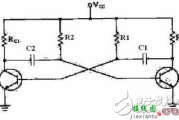
MSP430 按键接口电路图
 第1张")
 第2张")
 第3张")
相关文章
发表评论